Electromagnetic Eddy Current engineering is simply better by design
Variable frequency drives (VFDs) and DC drives operate by electronically altering the input power to control the speed of the motor. Eddy current drives, also known generically as magnetic drives, eddy current clutches or magnetic clutches are driven at a constant speed by an AC motor and utilize a simple electro-magnetic device to control torque and speed to the driven load.
Read About How Eddy Current Works
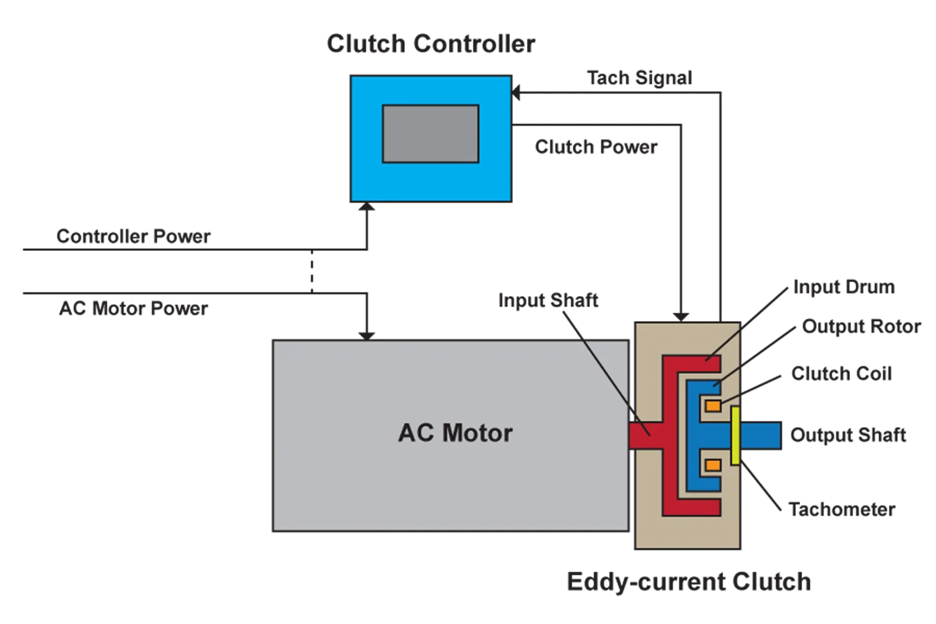
Horizontal machines can either be flange-coupled to the motor, or may be separately mounted, in a shaft-coupled configuration. In a typical vertical configuration (see diagram above), an ordinary induction motor is mounted atop the eddy current drive. The eddy current drive is built within a stationary frame of fabricated or cast steel, with a lower flange and shaft like that of a vertical motor. Within the frame are two concentric rotating members: The drum, shown in red, (sometimes called the ring) and the magnetic rotor (shown in blue), (sometimes referred to as the magnet or field).
The drum is a cylinder of magnetically permeable steel coupled directly to the motor shaft, and thus rotates at constant speed, determined by the speed of the motor. The motor shaft provides an axial and radial support bearing for the rotating drum.
The adjustable speed magnetic rotor is mounted concentrically within the drum, and is separated by bearings, which maintain an air gap between the i.d. of the drum and the o.d. of the magnet to a specified tolerance. The outer surface of the magnet consists of a series of magnetic poles having alternating north and south polarity which are magnetized at varying strength by a low-power DC current, referred to as excitation.
The excitation current flows to a coil which induces magnetic flux to the pole pieces, or in some designs, a series of individual windings on the individual pole pieces. Some models utilize carbon brushes and slip rings to deliver the current to the pole windings. As the rotating drum passes through the magnetic flux field in the air gap, a pattern of eddy currents is established in the drum’s steel. These currents in turn establish a magnetic field of their own, causing an exchange of torque from the drum to the magnetic rotor. It might be useful to envision that the magnetic rotor “chases” the drum.
The available torque is proportional to the excitation current flowing in the magnet’s coils. Thus, by increasing or decreasing this excitation current, speed is controlled. A tachometer-generator or other speed sensing device is provided for feedback to the controller, and for external reporting to a visible meter or central control system.
The excitation current is derived from an exciter/controller, normally supplied as a package with the eddy current drive. It derives power from a low voltage single phase source and utilizes an SCR bridge to develop the DC current used by the magnet coils. In general, this excitation requires less than 1% of the power being supplied to the driven pump load. The actual power that reaches the pump comes from the AC motor, not from this excitation.
The eddy current drive develops and maintains a smooth consistent torque so long as there is excitation current and at least some relative movement between the drum and the magnet. The differential between motor speed and output speed is referred to as “slip”. In pumping applications, the drive unit is chosen such that it can provide enough torque at 96% to 99% of motor speed, or conversely, 1% to 4% slip. This slip results in an equivalent percentage of loss, manifesting itself as heat in the drum, and dissipated into the cooling air. In centrifugal pump and fan applications, this slip loss, applied against a declining load as speed is reduced, results in a net loss very comparable to VFD performance.